


CAV II Grid Code
MSDG Grid Code — Greater than 500 kW and not exceeding 2 MW — Version 3.3, August 2024
Foreword
The purpose of this document is to assist the public to better understand the procedure for application, the requirements of the Grid Code and other related issues regarding Medium Scale Distributed Generation (MSDG).
Any prospective applicant willing to take advantage of the Medium Scale Distributed Generation (MSDG) Scheme is informed that:
- Compliance to this Grid Code shall be mandatory.
- The provisions of the Electricity Act 2005 and associated relevant Regulations shall be adhered to.
- The provisions of the Environment Protection Act 2002, Local Government Act 2011 and Finance Act 2013.
- This Grid Code will be reviewed and updated when the need arises.
Disclaimer
The Central Electricity Board’s (CEB) “Grid Code for Medium Scale Distributed Generator (MSDG) – Greater than 500 kW and not exceeding 2 MW”, including any periodic revisions, published on the CEB website, constitute the minimum technical requirements for the connection of an MSDG of size greater than 500 kW and not exceeding 2 MW to CEB’s 22 kV distribution network. The owner of the MSDG may be required to meet additional requirements to ensure that the interconnection meets all local regulations and is safe for use. The requirements set in this Grid Code are based on system conditions that may be subject to change. As such, these requirements shall only be used as a guide, subject to in-depth evaluation. CEB reserves the right to revise this Grid Code at any time. Any person wishing to make use of this Grid Code is invited to contact CEB before proceeding.
The CEB reserves the right to modify such technical specifications and requirements of the MSDG system and the MV switchgear before or during implementation of the MSDG connection process, in order to adhere to the latest operational and safety aspects of the network. The MSDG installation shall abide with the latest MSDG Grid Codes and standards at the time of implementation of the project.
Revisions
- Version 3.3 — August 2024: Grid Code reviewed by CEB; updates performed on applicable capacity, DC-to-AC ratio, applicable capacity for NVD protection, communication requirements, metering, applicable capacity for fault ride-through requirement, VT and CT requirements on 22KV Switchgear Arrangement, status and alarms.
- Version 3.2 — October 2019: Updates on Protection against relay malfunction (applicable on a case-to-case basis) and Inter-tripping protection.
- Version 3.1 — September 2019: Updates on MSDG High Voltage Switchgear, Protection and Communication Requirements, Metering, Guaranteed Operating Characteristics and Typical High Voltage Switchgear Panel layout.
- Version 3.0 — May 2016: Grid Code reviewed by Consultant and updates performed.
- Version 2.1 — December 2013: Added Chapter 4: Guaranteed Operating Characteristic and Chapter 5: Testing and Commissioning.
Chapter 1 — Purpose of the Grid Code
This Grid Code describes the technical criteria and requirements for the connection of distributed generation plants of capacity greater than 500 kW but not exceeding 2 MW to the CEB’s 22 kV distribution network.
The proposed capacity shall be the AC power output from the RE installation. Capacity capping on inverters shall be applicable as appropriate.
This Grid Code caters for the connection to the CEB distribution network and production of electricity by the following Renewable Energy Technologies (RETs):
- Photovoltaic (PV)
- Wind Turbine Generator (WTG)
- Hydroelectric Generator
- Biomass-based generator
Note: For the technical criteria and requirements for the connection of MSDG of capacity greater than 50 kW but not exceeding 500 kW, please consult the relevant grid code available on ceb.mu.
Chapter 2 — Connecting MSDG to the Grid
2.1 Connection Process
The MSDG connection process follows a structured administrative and technical sequence:
- While an MSDG scheme is open, a duly-filled MSDG Application Form and requested technical specifications must be deposited at the CEB SOLAR PHOTOVOLTAIC SCHEME (HOUSEHOLDS) -MSDG Unit, CEB Curepipe. The processing fee must be settled at the Cash Office.
- Analysis of the MSDG proposal with respect to MSDG Grid Code requirements and the applicable scheme, if any. An Engineering Review / System Impact Study is conducted where required. A network and interconnection survey by district and a joint site visit with all stakeholders is arranged as necessary.
- A Letter of Intent is issued with allocated capacity, along with an invoice for processing fees, cost for network reconstruction, etc. (as applicable). Where network works are required, a cost estimate is sent to the applicant.
- The applicant acknowledges all conditions of the Letter of Intent and settles the processing fee and costs for network reconstruction, etc. (as applicable). If the applicant does not agree to bear costs, the process ends.
- A joint site meeting is held with all stakeholders and the Connection Agreement is signed. The applicant settles the Connection Fee and all other charges as applicable. For MSDG >1 MW, all charges related to fulfilment of communication requirements carried out by CEB are invoiced to the applicant.
- A coordination meeting is held prior to the power cut for scheduling of works. CEB executes interconnection works during the power cut. All other required works are completed and the whole installation is verified.
- The applicant completes the MSDG installation within 12 months from the date the Connection Agreement is signed. Upon completion, the applicant submits a duly signed Certificate of Installation and an as-made schematic diagram. An invoice for Connection Fee, TTB, modem (if applicable) and testing of CTs is sent to the applicant. The applicant settles all required costs.
- Testing and Commissioning is performed by CEB.
2.2 Connection Capacity
The maximum capacity of MSDG that can be connected to a Medium Voltage (MV) feeder is termed the connection capacity of that feeder. Different feeders have different connection capacities depending on the electrical characteristics of the conductor used, the magnitude and temporal variation of feeder loading, and the proposed location of connection.
The feasibility to connect any MSDG to CEB’s 22 kV distribution network will need to be confirmed by an interconnection impact study conducted by the CEB on a case-to-case basis. In addition, the possibility of interconnecting any MSDG facility with variable power output shall be subject to the maximum amount of variable renewable energy-based power generation that can be accommodated while maintaining system stability and security.
Capacity allocation rules:
- Applications are processed strictly according to the date/time of settlement of the application processing fees (first in, first out).
- Authorised applications are allocated to the feeder subject to a favourable interconnection impact study.
- Allocated capacity remains valid for one (1) year from the date of the Connection Agreement.
- Failing to finalise the MSDG installation within one year results in automatic cancellation and the capacity is freed for other applicants.
Chapter 3 — MSDG Interconnection Requirements and Safety Aspects
3.1 Interconnection Facility Characteristics
The interconnection facility required for the MSDG facility consists of:
- The MSDG facility is connected to CEB’s 22 kV network through a switchgear panel and a step-up interconnection transformer.
- The “CEB Interconnection Facilities” are the facilities required to interconnect the Generation Facility to the CEB 22 kV Distribution System, located on the CEB side of the Point of Common Coupling (PCC) / Point of Delivery (A), as shown in Annex 7.
- The “MSDG Interconnection Facilities” are the facilities required to interconnect the Generation Facility to the CEB System, located on the Generation Facility side of the PCC / Point of Delivery (A), as shown in Annex 7.
3.2 22 kV System Parameters
The MSDG shall function and protect itself within the following range of voltages, currents and frequencies on the CEB grid.
Table 1 — Design Parameters under Normal Conditions
| Parameter | Values |
|---|---|
| Service Voltage | 23.0 kV and 20.5 kV (+4.5% and −7%) |
| System Earthing | Effectively earthed / Non-effectively earthed (contact CEB to confirm) |
| Frequency | 50.75 Hz and 49.25 Hz (50 Hz ± 1.5%) |
| Fault Level | 600 MVA |
Table 2 — Design Parameters under Incident and Emergency Conditions
| Parameter | Values |
|---|---|
| Service Voltage | 24 kV and 19.8 kV (+9% and −10%) |
| System Earthing | Effectively earthed / Non-effectively earthed |
| Frequency | 52.00 Hz and 47.00 Hz (+4% and −6%) |
| Fault Level | 600 MVA |
3.3 MSDG High Voltage Switchgear
The applicant shall construct, install, test and commission the complete 22 kV switchboard as per the default scheme shown in Annex 7 (i.e. both the CEB and Client side). CEB will take ownership of its side after the guarantee period. The switchgear shall have the following characteristics:
Table 3 — Switchgear Characteristics
| Parameter | Values |
|---|---|
| Nominal system voltage | 22 kV |
| Highest system voltage for equipment | 24 kV |
| Rated voltage | 24 kV |
| Impulse test voltage (1.2/50 μs) | 125 kV peak |
| Rated short circuit capacity | 16 kA rms (1 sec) |
| Electro-dynamic withstand | 40 kA peak |
| Busbar rating | 630 A |
3.4 MSDG Interconnection Transformer
The MSDG interconnection transformer shall be of vector group Dyn11 (Delta on High Voltage side, Star on MSDG side). The delta winding on the CEB side ensures that:
- The performance and sensitivity of the earth fault protection scheme at the CEB substation are not affected;
- Triple harmonics from the MSDG do not reach CEB’s network;
- The MSDG is provided some isolation from voltage sags due to single-line-to-ground faults, allowing it to better ride through voltage sags.
Alternative transformer vector groups may be used subject to CEB approval. The detailed specifications of the interconnection transformer are given in Annex 7. The transformer shall be approved by CEB prior to ordering.
3.5 Earthing Arrangement
Earthing systems shall be designed, installed, tested and maintained according to BS 7354 and BS 7430. Steps must be taken to prevent the appearance of hazardous step and touch potential when earth faults occur on the 22 kV network. The 22 kV earth electrodes and low voltage earth electrodes shall be adequately separated to prevent dangerous earth potentials being transferred to the low voltage network.
In the event that the applicant is allowed to operate independently and isolated from CEB’s system, the applicant shall ensure that the electrical and protection systems of the facility are designed to support such mode of operation. Safety of personnel and integrity of equipment shall be guaranteed at all times during both parallel and isolated modes of operation.
3.6 Protection Requirements
3.6.1 General Requirements
The coordination and selectivity of the protection system must be safeguarded even with the entrance of new generation into the system. The settings of all protections shall be proposed by the promoter and accepted by CEB. The protection system shall provide protection against fault occurring on both CEB’s network and the MSDG facility, including short circuit, earth faults and overloading conditions, and shall also prevent islanding of the CEB distribution feeder.
All protection relays shall be numeric type with event logging and disturbance recording capabilities. The MSDG owner shall maintain the protection system and keep spares of all relays used in the MV switchgear.
3.6.2 Interconnection Protection Scheme (50/51, 50N/51N, 59N)
The Interconnection Protection Scheme shall consist of: (i) Multi-step instantaneous/time-delayed and IDMT overcurrent (50/51); (ii) Multi-step instantaneous/time-delayed and IDMT earth fault (50N/51N); (iii) Neutral Voltage Displacement (59N).
Protections 50/51 and 50N/51N shall act on the CEB Interconnection Circuit Breaker (CB1). The 59N shall act on all client’s outgoing circuit breakers.
3.6.3 Anti-Islanding Protection
The MSDG shall cease to energise CEB’s network within 0.5 seconds of the formation of an island. The following protection functions and settings are required:
| Parameter | Symbol | Trip Setting | Clearance |
|---|---|---|---|
| Overvoltage | U>> | Vφ-φ + 9% | 0.2 s |
| Overvoltage | U> | Vφ-φ + 6.0% | 1.5 s |
| Undervoltage | U< | Vφ-φ − 10% | 3.0 s |
| Overfrequency | f> | 52 Hz | 0.5 s |
| Underfrequency | f< | 47 Hz | 3.0 s |
| Loss of Mains — ROCOF | LoM | 2.5 Hz/s | 0.5 s |
| Loss of Mains — Vector Shift | LoM | 10° | 0.5 s |
The anti-islanding protection shall act on CB4 (MSDG circuit breaker). For MSDG ≥1 MW, inter-tripping facility using fiber optic cables or wireless communication is also required (see Section 3.6.5).
3.6.4 Inter-tripping Protection
An inter-tripping and interlocking system shall ensure that tripping of the CEB 22 kV Circuit Breaker (on fault, open locally or remotely) shall inter-trip ALL the Client outgoing 22 kV Circuit Breakers instantaneously. Closing of the CEB 22 kV Circuit Breaker is ONLY allowed if ALL Client 22 kV Circuit Breakers are in the open position.
3.6.5 Inter-tripping for MSDG ≥1 MW
The inter-tripping scheme shall be designed and pre-wired such that tripping of the interconnecting feeder circuit breaker in the CEB 22 kV substation results in the tripping of CB1. For solar PV MSDG ≥1 MW:
- Daytime: Upon tripping of the 22 kV circuit breaker at the CEB substation on fault, CEB System Control operator shall open CB1 remotely. CB1 inter-trips CB2. Upon supply restoration, CEB operator shall reclose CB1 remotely and liaise with the MSDG contact person to reclose CB2 locally.
- Night-time: Upon tripping of the 22 kV circuit breaker, CEB System Control operator shall not open CB1 as there is no PV generation at night.
For MSDG using RE technologies other than solar PV, generation occurs throughout the day and night; hence, CB1 shall be opened remotely irrespective of the time of the fault.
3.6.6 Protection Against Relay Malfunction
The watchdog function of the protection relay shall issue an alarm and trip the circuit breaker on which the protection relay normally acts in case of a malfunction. For MSDG ≥500 kW, this alarm signal (if required by CEB) shall be transmitted to the interconnecting CEB substation via fiber optic channel or wireless communication.
3.6.7 Protection Settings: Grading and Discrimination
For MSDG >500 kW, the applicant shall submit to CEB appropriate settings for grading and discrimination of the interconnecting protection (22 kV circuit breaker, CEB side) with the upstream CEB substation protection. The applicant shall also submit to CEB the fault contribution (both single-phase to earth and three-phase) from the generating plant on the 22 kV side.
Additionally, Table 4 below shows the NVD trip settings for the Neutral Voltage Displacement relay required for all MSDG >500 kW connected via MV switchgear:
| Parameter | Symbol | Trip Setting | Clearance Time |
|---|---|---|---|
| Neutral Voltage Displacement (59N) | NVD | When neutral point voltage displacement on the 22 kV side exceeds 10% of 22 kV/√3 (1,270 V) | 5.5 s |
3.7 Additional Protection and Safety Requirements
The following requirements are additional to the mandatory protections above and apply to all MSDG irrespective of the generation technology used:
- Appropriate interlocking shall be incorporated between the circuit breakers on the CEB and client side (per IEC 62271-200) to prevent the option of mechanically closing CB1 onto a live busbar on the client side via a mechanical interlocking system between CB1 and CB2.
- For MSDG containing synchronous and/or induction machines: a dead-bus/live-line check synchronism relay shall be provided to prevent remote/electrical closure of CB1 as long as the MSDG-side 22 kV busbar is energised.
- Check Synchronising shall be provided on all generator circuit breakers and any other circuit breakers (including LV circuit breakers), unless interlocked, that are capable of connecting the MSDG plant to CEB’s network.
3.8 Re-connection
Following a protection-initiated disconnection, the MSDG is to remain disconnected from the network until the voltage and frequency at the supply terminals has remained within the nominal limits for at least 3 minutes. Automatic re-connection is only allowed when disconnection was due to operating parameters being outside the normal operating range. If disconnection was caused by malfunctioning of any devices within the MSDG installation, manual re-connection with CEB authorisation is required.
3.9 Uninterruptible Power Supply (UPS)
An online UPS is required to ensure that the protection, measurement, control and communication systems operate without interruption for a minimum duration of 3 hours after loss of CEB power supply. In the event of loss of the secured auxiliary supply, all Client 22 kV circuit breakers shall be tripped until remedial actions are taken.
For MSDG ≥1 MW, all equipment used for the transmission of signals and commands (PLC, modem, router, etc.) between the MSDG site and CEB System Control shall be supplied from a separate UPS to that of the protection systems.
3.10 Indication, Alarms and Instrumentation
The alarm and trip facilities shall have local indication and, for MSDG ≥1 MW, an additional set of potential-free contacts for onward transmission of the alarm/trip signals to the CEB Substation. For MSDG ≥1 MW, a local SCADA system shall be installed to allow monitoring and control of the MSDG installation.
External indicator lamps shall be installed for MSDG >500 kW to indicate parallel operation with the CEB distribution network: a lighted red lamp shall indicate parallel operation; a lighted green lamp shall indicate isolated operation.
Panel instrumentation shall include transducer-fed voltmeter, ammeter, MW, MVAr (indicating import and export), and appropriate test blocks for current and voltage circuits.
3.11 Communication Requirements
The MSDG owner shall install communication equipment for secured transfer of operating data and protection and control signals. For MSDG ≥1 MW, a fiber optic cable link shall connect the MSDG plant to the corresponding 22 kV substation (as per Annex 9). The applicant bears the full cost of procurement, installation, testing, commissioning and maintenance of the communication system.
The following data shall be transmitted in real time from the Generation Facility to the CEB Substation:
- Load Break Switch status (OPEN/CLOSED) for each incomer (if available)
- Circuit Breaker CB1 status (open/close)
- Outgoing Circuit Breaker CB2 and CB4 status (open/close)
- Alarms: Protection Operated, Protection relay not healthy, SF6 Alarm, UPS Alarms, Door Alarm, Inter-tripping signal, Remote/Local CB1 signal, Other alarms (grouped)
- MW, MVAr at the import/export interface (calculated using 3-phase voltages and current on Phase 2)
- Voltage level of the 22 kV busbar (Line-to-line between phases 1 and 2)
- Current at the import/export interface (Phase 2)
For MSDG >1 MW, remote control commands shall also be provided (Load Break Switch OPEN/CLOSE, CB1 open/close).
Wireless Communications
Where wireless communications are used, the system shall meet the following minimum requirements:
- Use of latest 3G/4G/LTE or newer technology for the frequency bands used in Mauritius
- Microwave link as main channel and 3G/4G/LTE as backup; seamless failover; SLA of 4 hours
- Dual SIM capability with automatic switching between network operators
- All 3G/4G/LTE channels in VPN tunnel mode (Open VPN or equivalent)
- Minimum two routers configured as main and hot-standby; data rate ≥85 kbps download / 42 kbps upload
- Configuration interface protected by password; auto-recovery mechanism
3.12 Metering
The CEB meter, CTs and VTs shall have at least the following accuracy classes:
| MSDG Installation | Connected to LV Network | Connected to MV Network |
|---|---|---|
| Not exceeding 500 kW | Class 1 | Class 0.5 |
| Greater than 500 kW and not exceeding 2 MW | — | Class 0.5 |
| Greenfield | — | Class 0.2 |
The CEB meter shall have separate registers for import and export of energy. All CEB metering circuits shall be totally separate from the MSDG promoter’s circuits. Toroidal CTs will not be accepted for HT metering purposes.
A second production meter shall be installed by CEB inside the MSDG installation. All meters and related equipment (CTs, VTs, TTB) shall be housed in a secured metering cabin fitted with a 13A power socket protected by a 2A circuit breaker and fed from a secured source of supply. The MSDG promoter shall first seek CEB’s approval for CT/VT specifications before ordering and send equipment to CEB’s Meter Lab Section for testing prior to installation.
3.13 Preventive and Corrective Maintenance
3.13.1 Generation Schedule
MSDG ≥1 MW shall facilitate a generation forecast to CEB (day-ahead, hourly values by default). MSDG <1 MW does not need to communicate a generation forecast.
3.13.2 Generator Maintenance
MSDG ≥1 MW shall submit annual preventive maintenance plans to CEB for approval, with monthly updates and at least 15 days’ advance notice for any planned changes. For corrective maintenance, CEB shall be notified within 3 hours of the occurrence. MSDG <1 MW is not required to submit maintenance plans.
3.13.3 Network Maintenance
Maintenance works or faults on the feeder may prevent the MSDG from exporting. No compensation shall apply for loss of generation due to preventive and corrective maintenance in CEB’s network. CEB shall communicate its maintenance plans to MSDG promoters ≥500 kW before the planned maintenance action takes place.
3.14 Safety, Isolation and Switching
3.14.1 Safety Procedures for High Voltage Switchgear
CEB personnel shall strictly abide by the “CEB T&D Safety Rules” in compliance with the Occupational Safety and Health Act 2005. The MSDG promoter shall:
- To comply with Section 7(2) of the OSH Act 2005 — where total generation exceeds 750 kW, the employer shall employ a Registered Professional Engineer in general charge of all such machinery.
- Appoint and train competent persons responsible for HV switchgear operation; maintain an updated list communicated to CEB.
- Display an up-to-date schematic diagram of the switchgear in the switchgear room.
- Clearly number and label all switchgear panels.
- Before any work, the competent person shall certify switching operations carried out on the “Certificat de Consignation” (Annex 2) and remit the original to the CEB counterpart.
- Secure switchgear with personal padlocks and affix proper warning signs.
3.14.2 Safety Concerns
- Both the mains supply and the generator must be securely isolated before electrical work is performed. Adequate labelling must warn that the installation is connected to another source of energy.
- For PV: cover all modules before working on circuits upstream of the isolation point. For WTG: restrain the turbine from turning.
- The manufacturer/supplier of the MSDG shall certify CE compliance or equivalent for electrical safety and EMC.
- All maintenance shall follow the manufacturer’s recommended safety procedures.
- CEB personnel must be warned of switching procedures applicable to the MSDG; these must be clearly displayed and visible at the MSDG site.
3.14.3 Electromagnetic Emission / Immunity
The MSDG shall comply with the requirements of the EMC Directive and in particular the product family emission standards.
3.14.4 Labels
A CEB-standard MSDG warning label (Figure 1) shall be affixed at the following locations:
- The nearest 22 kV pole on which the switch fuses are installed (or the Ring Main Unit in case of underground networks)
- Switchgear room entrance
- The transformer cabin door and fence
- The metering cabin and box
- The CEB incoming feeder cubicle, voltage transformer cubicle, interconnection circuit breaker cubicle
- Any other locations found necessary by CEB
3.15 Documentation
Up-to-date information must be displayed at the MSDG installation, including:
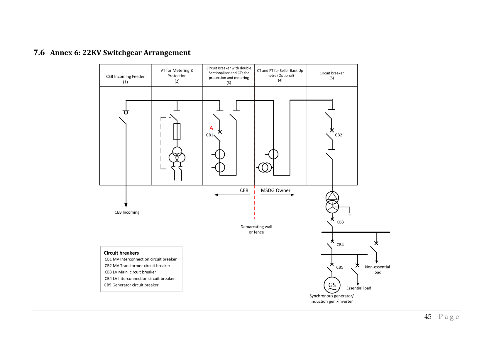
- A circuit diagram showing the relationship between the MSDG and CEB’s incoming feeder as shown in Annex 6, and showing by whom the generator is owned and maintained
- All relevant information related to fault contribution to all different types of faults from the MSDG; a copy of the protection test results obtained during commissioning must be delivered to CEB
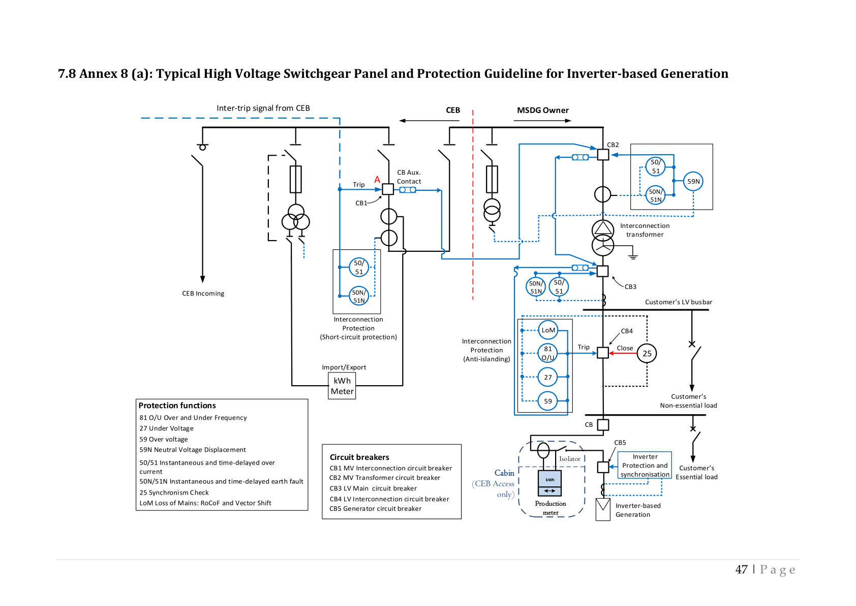
- A summary of the interconnection and anti-islanding protection settings (as per Annex 8)
- Switching operation procedures at the MSDG facility
- Maintenance requirements and maintenance services available
- A certificate signed by the maintenance contractor confirming: solar PV/WTG/hydro, switchgear, UPS and interconnection transformer meet the requirements of this Grid Code; client name and address; site address; contractor name and contacts; list of key components; estimation of system performance; maintenance schedule
3.16 Information Plate
Each MSDG installation shall display an information plate showing: (a) manufacturer’s name or trade mark; (b) type designation or identification number; (c) rated power; (d) nominal voltage; (e) nominal frequency; (f) phases; (g) power factor.
3.17 Electrical Contractor / Installer
The MSDG shall be installed in accordance with the manufacturer’s instructions. The installer shall consider all aspects including: maximum demand and generator output; type of earthing arrangement; nature of the supply; external influences; compatibility, maintainability and accessibility; protection against electric shock and thermal effects; protection against overcurrent; isolation and switching; selection and installation issues.
The installer shall affix a label indicating the next scheduled maintenance and inform CEB to update the MSDG register. The installer shall be skilled in the field of MSDG installations and possess an MQA-approved qualification or equivalent in electrical installation and renewable energy installations acceptable to CEB.
3.18 Standards and Regulations
All electrical apparatus, materials and wiring shall comply with the Electricity Act, the CEB Act, Electricity Regulations, this Code and the following standards (latest editions apply):
PV Modules
- IEC TS 62804-1/-2 — PV modules: potential-induced degradation testing
- EN 50380 — Datasheet and nameplate information for photovoltaic modules
- IEC 61215 — Crystalline silicon terrestrial PV modules — Design qualification and type approval
- IEC 61646 — Thin-film terrestrial PV modules — Design qualification and type approval
- IEC 61701 — Salt mist corrosion testing of PV modules
- IEC 61730 — PV module safety qualification
- IEC 61853-1 — PV module performance testing and energy rating — Part 1
PV Inverters
- EN 50524 — Data sheet and name plate for photovoltaic inverters
- IEC 61683 — PV Systems — Power conditioners — Procedure for measuring efficiency
- IEC 62109 — Safety of power converters for use in photovoltaic power systems
- IEC 62116 — Test procedure for islanding prevention measures for utility-connected PV inverters
Grid-Connected PV Systems
- EN 50438 — Requirements for connection of micro-generating plants in parallel with public LV distribution networks
- ER G59/3 — Recommendations for connection of generating plant to distribution systems of licensed DNOs
- ER G83/2 — Recommendations for connection of type tested small-scale embedded generators (up to 16 A per phase)
- EN 50521 — Connectors for photovoltaic systems — Safety requirements and tests
- IEC 61727 — PV systems — Characteristics of the utility interface
- IEC 61836 — Solar PV energy systems — Terms, definitions and symbols
- IEC 62093 — Balance-of-system components for PV systems — Design qualification natural environments
- IEC 62446-1 — PV systems — Requirements for testing, documentation, and maintenance — Part 1: Grid-connected systems
- IEC 60904-1 — Photovoltaic devices — Part 1: Measurement of PV current-voltage characteristics
- IEEE P1547 — Series of Standards for Interconnection of Distributed Resources
Wind Turbine Generators
- IEC 61400-21 — Wind Turbines — Part 21: Measurement and assessment of power quality characteristics of grid-connected wind turbines
General Engineering Standards
- BS 7354 — Code of Practice for Design of high voltage open terminal stations
- BS 7430 — Code of Practice for Protective Earthing of electrical installations
- IEC 60068-2 — Environmental testing of specimen to withstand specific severities
- IEC 60076 — Power transformers — ALL PARTS
- IEC 60228 — Conductors of Insulated Cables
- IEC 60364-1 — Low-voltage electrical installations — Part 1: Fundamental principles
- IEC 60364-5-54 — Low-voltage electrical installations — Earthing arrangements and protective conductors
- IEC 60364-5-55 — Electrical installations of buildings — Part 5-55: Other equipment
- IEC 60502-1 — Power cables with extruded insulation for rated voltages from 1 kV up to 30 kV
- IEC 60664-1 — Insulation coordination for equipment within low-voltage systems — Part 1
- IEC TR 60909-1 — Short circuit currents in three-phase AC systems — Factors for calculation
- IEC 62208 — General requirements for empty enclosures for LV switchgear and controlgear assemblies
- IEC 62305-3 — Protection against lightning — Part 3: Physical damage and life hazard in structures
- IEEE C37.90 — Standard for Relays and Relay Systems Associated with Electric Power Apparatus
Power Quality
- IEC 61000-3-2 — EMC — Limits for harmonic current emissions
- IEC 61000-3-3 — EMC — Limitation of voltage changes, fluctuations and flicker — Equipment ≤16 A per phase
- IEC TR 61000-3-7 — EMC — Assessment of emission limits for fluctuating installations on MV, HV and EHV power systems
- IEC 61000-6-1 — EMC — Generic standards — Immunity for residential, commercial and light-industrial environments
- IEC 61000-6-3 — EMC — Generic standards — Emission standard for residential, commercial and light-industrial environments
- IEEE 519 — Recommended practice and requirements for harmonic control of electric power systems
Chapter 4 — Guaranteed Operating Characteristics
Installers are required to ensure that all proposed equipment has the capabilities to implement all the requirements of the MSDG Grid Code, especially the requirements stipulated in this chapter.
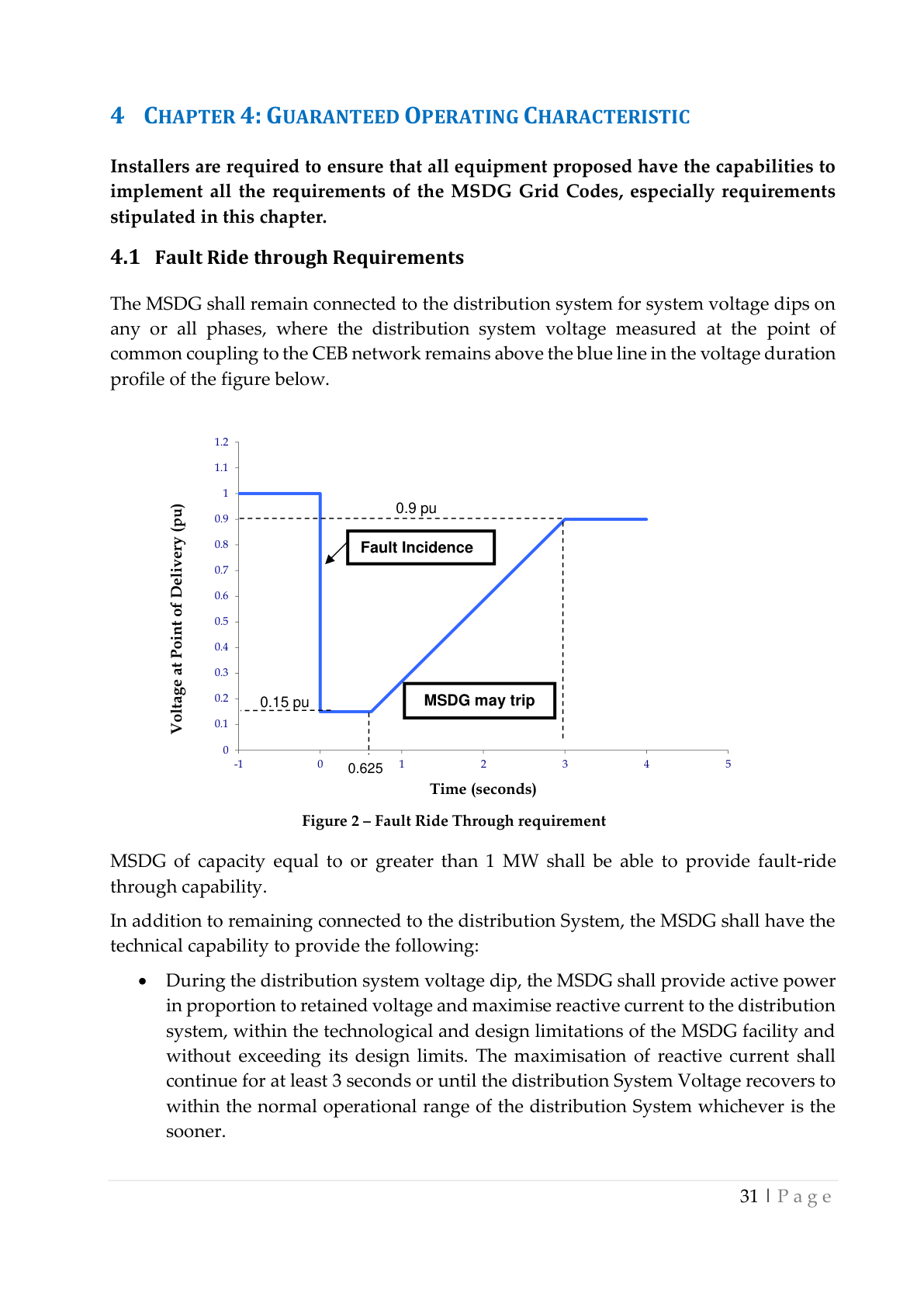
4.1 Fault Ride Through (LVRT) Requirements
The MSDG shall remain connected to the distribution system for system voltage dips on any or all phases, where the distribution system voltage measured at the point of common coupling remains above the boundary shown in Figure 2 below. MSDG ≥1 MW shall be able to provide fault-ride through capability.
In addition to remaining connected, the MSDG shall provide active power in proportion to retained voltage and maximise reactive current injection to the distribution system for at least 3 seconds, or until the distribution system voltage recovers to within the normal operational range. The LVRT curve shall be coordinated with the under-voltage protection settings (Table 5).
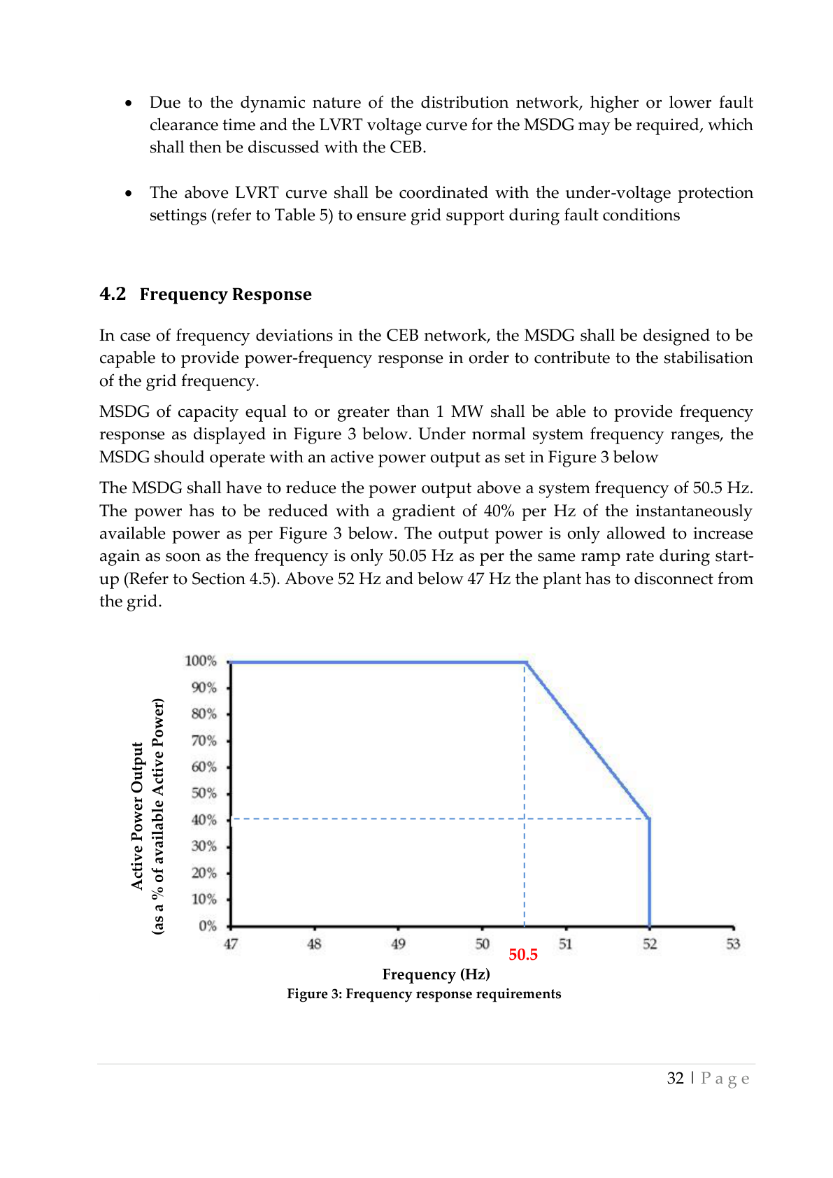
4.2 Frequency Response
MSDG ≥1 MW shall provide power-frequency response to contribute to the stabilisation of the grid frequency. Under normal system frequency ranges, the MSDG shall operate at maximum available active power output. The MSDG shall reduce power output above a system frequency of 50.5 Hz at a gradient of 40% per Hz of the instantaneously available power. The output power is only allowed to increase again once frequency returns to 50.5 Hz or below. Above 52 Hz the MSDG shall disconnect within 0.5 seconds. Below 47 Hz for longer than 0.5 seconds, the MSDG is permitted to disconnect.
4.3 Reactive Power Capability
MSDG ≥1 MW shall be equipped with reactive power control functions that are mutually exclusive — only one mode active at a time:
- Power Factor Control: Maintains a fixed power factor as specified by CEB
- Reactive Power Control: Regulates reactive power to a CEB-defined set-point
- Voltage Control: May be required if previously agreed with CEB on a case-by-case basis
All MSDG ≥500 kW shall be designed to supply rated power for power factors ranging between 0.95 lagging and 0.95 leading, available from 20% of rated power.
4.4 Power Quality
The MSDG facilities and equipment shall not cause excessive voltage excursions nor introduce excessive distortion to the sinusoidal voltage or current waves.
4.4.1 Voltage Flicker
The MSDG installation shall not cause abnormal flicker beyond the limits defined in IEEE 519 at the Point of Common Coupling.
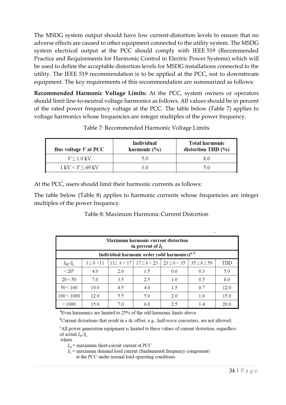
4.4.2 Harmonics
The MSDG system output at the PCC shall comply with IEEE 519. The IEEE 519 recommendation is to be applied at the PCC, not to downstream equipment.
4.4.3 Voltage Step Change
Step voltage changes caused by the connection and disconnection of generating plants at the distribution level shall not exceed ±3% for infrequent planned switching events or outages and ±6% of the nominal voltage of 22 kV for unplanned outages such as faults.
4.4.4 Surge Withstand Capability
The interconnection system shall have surge withstand capability (oscillatory and fast transient) in accordance with IEC 62305-3. The design of control systems shall meet or exceed the requirements of IEEE C37.90.
4.4.5 Voltage Unbalance
The contribution to the level of voltage unbalance at the PCC from any MSDG installation shall be less than or equal to 1.3%.
4.5 Ramp Rate Limits
MSDG ≥1 MW shall have controlled ramp up/down: positive ramp rate only during start-up; negative ramp rate during shutdown of the MSDG facility.
- 1-minute maximum ramp rate: MSDG’s installed capacity (MW) divided by 5
- Ramp rate settings shall be approved by CEB prior to testing and commissioning; minimum two weeks’ notice for any subsequent changes
Chapter 5 — Testing and Commissioning
5.1 Introduction
The applicant shall perform the testing and pre-commissioning phases of the MSDG as per relevant standards. The applicant shall keep written records of all test results and protection settings. The interconnection protection of the MSDG shall be regularly tested and maintained. Ad-hoc tests may be required by CEB for purposes such as harmonic assessment, voltage rise, protection operation following system changes, and fault investigation.
5.2 Testing and Pre-Commissioning
For Greenfield projects, the applicant shall submit testing and pre-commissioning procedures and plans to CEB for approval at least 3 months prior to the Scheduled Commercial Operation of the MSDG Facility.
5.2.1 Testing Phase — PV Facility
- Earthing continuity of array frame to earth and connection to main earthing terminal
- Polarity of each module string
- PV string Open-Circuit Voltage (Voc) test
- PV Short-Circuit Current (Isc) test
- PV array insulation resistance test
- Operational test of PV string current; functional test; performance verification
- Cable insulation resistance testing
5.2.2 Testing Phase — WTG Facility
- 6-hour test run with the generator connected to the grid
- Demonstration of WTG vibration level below acceptable limits
- Test of trip function when WTG is generating and grid loss occurs
- Test of over-speed trip function of each WTG; test of yaw drives; functional test; performance verification
5.2.3 Pre-Commissioning Phase
Pre-commissioning tests shall be performed in the presence of CEB and shall include at minimum:
- Demonstration of satisfactory operation of power measurement equipment
- Functional tests of the relay protection and verification of settings
- Demonstration of satisfactory operation of internal reticulation
- Pressure tests on 22 kV switchgear
- Reactive Power Capability test
- Power Quality Test as per IEC 61400-21
- Anti-islanding test
- Test of the facility to withstand step load change
5.3 Power Quality
After satisfactory testing and pre-commissioning and submission of the Certificate of Installation, CEB will perform tests to ensure the facility is compliant with Section 4.4 of this Grid Code.
5.4 Commissioning Engineer
Given the size and complexity of the MSDG installation, testing and pre-commissioning shall be performed by a Registered Professional Engineer. The RPE shall inspect and test the installation for compliance with existing requirements and report results to CEB. The MSDG Owner shall then submit a duly signed Certificate of Installation. Upon compliance, CEB shall prepare a Certificate of Compliance confirming that the installation complies with the requirements of this Grid Code, has been found fit for connection to the Grid, and is commissioned after the signature of the Connection Agreement.
Chapter 6 — Compliance with the Code
In case of non-compliance with any of the technical provisions in this Grid Code, CEB shall inform the owner in writing of the discrepancies. The MSDG owner shall have 90 days to rectify the discrepancies. Failing to do that, CEB shall be entitled to disconnect the MSDG installation.
CEB shall be entitled to disconnect the MSDG facility without prior notification if the installation conditions are harmful or create unavoidable risks for safety. CEB shall not be responsible for any damage if such disconnection requires the disconnection of other loads connected to the same connection as the MSDG.
Reconnection of the MSDG shall require that CEB certifies that the installation complies with this Grid Code. Fees applicable shall be the same as the standard reconnection fees.
Chapter 7 — Annexes
Annex 1 — Abbreviations and Definitions
- “AC” or “a.c.” — Alternating Current
- “Applicant” — A producer of electricity through an MSDG installation
- “CEB” — Central Electricity Board
- “Circuit breaker” — A switching device capable of making, carrying, and breaking currents under normal conditions and also making, carrying for a specified time, and breaking currents under abnormal conditions such as short circuit
- “DC” — Direct Current
- “DG” — Distributed Generation
- “Distributed generation” — Electric generation facilities connected to the Utility network at the PCC
- “Flicker” — A variation of input voltage sufficient in duration to allow visual observation of a change in electric light source intensity
- “Fault” — A physical condition that causes a device, component, or element to fail to perform in a required manner
- “Frequency” — The number of complete cycles of sinusoidal variation per unit time
- “Greenfield project” — An MSDG installation at a location without an existing connection point
- “Grid” — CEB’s network that brings electricity from power stations to consumers
- “GPRS/VPN” — Virtual Private Network set up over a General Packet Radio Service (GPRS)
- “Harmonic distortion” — Continuous distortion of the normal sine wave, typically caused by nonlinear loads or inverters; measured in Total Harmonic Distortion (THD)
- “HT” — High Tension (systems normally operating at voltage exceeding 1000 V AC or 1500 V DC)
- “Registered Professional Engineer” — A person registered as a Professional Engineer under the Registered Professional Engineers Council Act (Mauritius)
- “Installer” — A person skilled in MSDG installations, possessing an MQA-approved qualification or equivalent acceptable to CEB
- “Islanding” — A condition in which a portion of CEB’s network is energised by one or more MSDGs through their PCC(s) while electrically separated from the rest of the system
- “Isolated Generation” — A condition where the electrical path at the PCC is open and the MSDG continues to energise local loads
- “kV / kVA / kW / kWh” — Kilovolt / Kilovolt Ampere / Kilowatt (1,000 W) / Kilowatt hour
- “LV” — Low Voltage (systems normally operating at voltage not exceeding 1000 V AC or 1500 V DC)
- “MSDG” — Medium Scale Distributed Generation — greater than 500 kW up to 2000 kW
- “MW” — Megawatt (1,000,000 W)
- “Parallel operation” — A condition where the MSDG is operating while connected to CEB’s network
- “PCC” — Point of Common Coupling — the point at which an MSDG is connected to CEB’s network
- “Power factor” — Ratio of real to total apparent power (kW/kVA) expressed as a decimal or percentage
- “Producer” — A producer of electricity through any MSDG installation or the owner thereof
- “PV” — Photovoltaic
- “RE” — Renewable Energy
- “SWC” — Surge Withstand Capability — the immunity of equipment to fast and repetitive electrical transients
- “THD” — Total Harmonic Distortion
Annex 2 — Certificat de Consignation (Specimen)
A Certificat de Consignation is required before any work can be performed on either side of the 22 kV switchgear panel. The competent person performing switching operations shall certify the operations carried out on this approved form and remit the original to his CEB counterpart, who may then proceed with the work in accordance with the applicable safety procedures.
The certificate includes fields for: date and time; name of competent person; description of switching operations performed; equipment switched (panel numbers, CB designations); signatures of the client and CEB representatives; and confirmation that appropriate isolation, padlocking and warning signs are in place.
Annex 3 — CEB Fees
The MSDG will be connected to CEB’s 22 kV network through a High Voltage switchgear and metered on the high-voltage side. The applicant shall bear fees for processing applications and preparation of cost estimates for network construction or modification. The list of fees is available on the CEB website.
Fees include: Processing fee; Connection Fee; Engineering Review / Distribution Study; Revision of Estimate. Network construction / modification costs are determined after the engineering review.
Annex 4 — Certificate of Installation
The applicant/installer shall submit a duly signed certificate (with the company’s header and seal) to CEB. The MSDG installation shall be certified by a Registered Professional Engineer (CRPE Mauritius). The certificate shall include:
- Name of Installer Company
- Name of Registered Professional Engineer; RPEM No.; Signature; Date; Seal of Installer Company
- Name of Applicant; Signature of Applicant; Date
- MSDG Serial No.: MSDG/_______________
Annex 5 — Certificate of Compliance
This certificate confirms that the MSDG installation with an installed capacity of [kW], situated at [address] in the name of [Applicant/Company name] bearing Serial No. [MSDGX/XX/XXX] has been found compliant with the requirements of the MSDG Grid Code by the CEB Representatives hereunder and is fit for connection to the Grid. The installation shall be commissioned after the signature of the Connection Agreement.
The Certificate of Compliance is signed by representatives from:
- Distribution Network
- Meter Installation
- MSDG-CEB SOLAR PHOTOVOLTAIC SCHEME (HOUSEHOLDS) Unit
- Safety and Health Section
- C&M Section
Annex 6 — 22 kV Switchgear Arrangement
The following single-line diagram shows the required 22 kV switchgear arrangement at the MSDG interconnection facility, with the demarcation between CEB equipment and MSDG Owner equipment:
Annex 7 — Interconnection Facility Description
Responsibilities and costs for the interconnection facility:
- CEB shall be responsible for the construction, installation and commissioning of the 22 kV interconnection line forming part of the CEB Interconnection Facilities.
- The applicant shall be responsible for acquiring the right of way for the interconnection 22 kV line, and for the construction, installation, testing and commissioning of the complete 22 kV switchboard (CEB and MSDG side). CEB will take ownership of its side after the guarantee period.
- The applicant shall bear the cost of procurement, installation, testing and commissioning of both CEB and MSDG Interconnection Facilities.
- The applicant shall be responsible for all civil works including cable trench, draw-pits, PVC pipes, and construction of the switchgear room as per CEB specifications.
- The applicant shall own and be responsible for the operation, maintenance and repair of MSDG’s Interconnection Facilities.
Annex 8 — Typical HV Switchgear Panel and Protection Guideline
The following diagram shows the typical high voltage switchgear panel and protection guideline for inverter-based MSDG generation (Annex 8a):
Annex 9 — Communication Requirements
The fiber optic communication system shall connect the MSDG facility to the 22 kV feeder substation for all MSDG ≥1 MW. The system shall transmit all required status, measurement, alarm and control signals as specified in Section 3.11 of this Grid Code. Detailed communication data points, protocols and interface specifications shall be agreed with CEB prior to procurement and installation. All costs of procurement, installation, testing, commissioning and maintenance of the communication system are borne by the MSDG promoter.